
A larger scale version appears in Chapter 11 and is available for download in the Download Files area reached from the Site navigation bar.
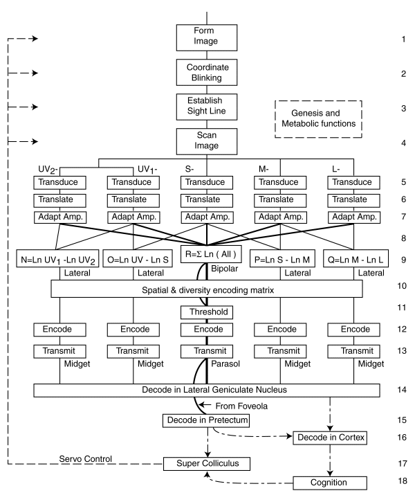
The figure attempts to show the signal flow diagram for a generic visual system. Not all of the features shown are used in every species or family of animal system. Many detailed features do not appear at this level of detail.
The central channel, R, represents the luminance channel of vision. Tetrachromats use all of the spectral channels shown above level 5 of the figure. Long wavelength trichromats, such as humans, use only the right three channels. Short wavelength trichromats, such as many insects, use only the left three channels. The ultraviolet channel may be split into two spatially orthogonal channels in order to support navigation by polarization detection.
The importance of servomechanism feedback in vision is emphasized by the feedback paths shown on the left.
The labels shown below individual boxes are those generally associated with the function in the literature. In some cases, the designations may not be exclusionary.
The individual adaptation amplifiers in each spectral channel should be noted.
Note the circular loops associated with signals from the foveola. They indicate that these signals are treated differently from those of the majority of the retina. They are not passed through the diversity encoding function associated with most signal projection paths and they do not pass through the LGN on their path to the cortex.
The majority of the signal paths within the visual system involve signal differencing rather than summation. The performance of the chrominance system of vision cannot be described in terms of additive color principles. Only the luminance channel can be described using additive color principles. In both cases the signals are converted to logarithms before algebraic manipulation.
The complete discussion of this figure is found in Section 11.6.3 of Chapter 11.
Return to the website home page