The following two figures are presented here at reduced scale (resolution) to accommodate a browser. Larger scale versions appear in Chapter 15 and are available for download in the Download Files area reached from the Site navigation bar. The figure is actually an expanded portion of part of Figure 11.6.4 in Chapter 11.

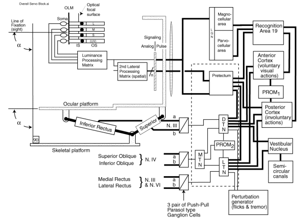
The figure shows the servomechanism signal flow diagram for a higher chordate. The diagram is complex because it shows both the involuntary (inner) servo loop as well as the voluntary (outer loop which includes the cortex).
Signal manipulation within the inner (involuntary) servo loop focuses on the Precision Optical System shown within the dotted box. All of the elements to the left of the dotted box are common to both servo loops.
The elements particular to the voluntary servo loop (including some higher level but still involuntary functions) are shown above and to the right of the dotted box.
The vestibular system which provides an inertial reference for the system is shown at the lower right. At the very bottom of the figure is the perturbation generator crucial to the operation of the visual system as an imager.
The angle alpha is shown twice to emphasize the angle between the line of sight and the skeletal platform is controlled by the oculomotor system.
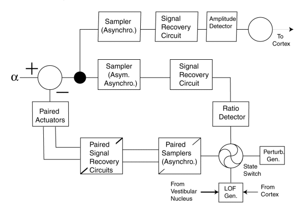
The following figure presents the same system as above in simplified form and using the language of a servomechanism specialist. Only the inner loop is shown explicitly closed. Note however, the signal going to the cortex in the upper right and returning from the cortex in the lower right.

The asynchronous nature of the signal samplers is an important feature of the system. The state switch is controlled by a complex program based on calculatons performed in the Line of Fixation (sight) generator, LOF.
The complete discussion of this figure is lengthy. It can be found in Section 15.2.4 of Chapter 15.